


1 Scope
This procedure is used to determine the resistanceto coating adhesion loss of coated surfaces ofaluminum, plastic, steel, and other substrates when subjected to a wet steam blast similar to thatproduced by vehicle wash equipment.
Note: Nothing in this standard supersedesapplicable laws and regulations.
Note: In the event of conflict between the English
and domestic language, the English language shall take precedence.
1.1 Purpose. To determine the resistance to coating adhesion loss of coated surfaces of aluminum, plastic, steel, and other substrates when subjected to a wet steam blast similar to that produced by vehicle wash equipment.
1.2 Foreword. Not applicable.
1.3 Applicability. Painted exterior components of vehicle.
2 References
Note: Only the latest approved standards are applicable unless otherwise specified.
2.1 External Standards/Specifications.ISO 2808
2.2 GM Standards/Specifications.
3 Resources
3.1 Facilities. Not applicable.
3.2 Equipment.
3.2.1 Test Equipment and Material.
3.2.1.1 Scribe Tool. A straight-shank tungsten carbide tip, lathe cutting tool or carbide-tipped pencil type tool with tip angle of 60 ± 15 degrees or equivalent.
3.2.1.2 Razor blade.
3.2.1.3 Water Bath. Water bath at 38 ± 2°C temperature with 5 ppm maximum dissolved solids as measured utilizing a suitable dissolved solids meter.
3.2.1.4 Freezer capable of maintaining -29 ± 3°C temperature.
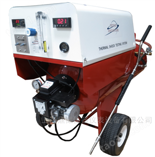
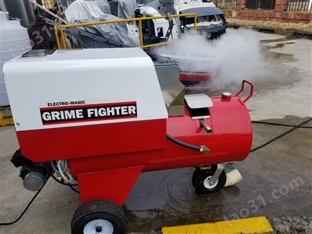
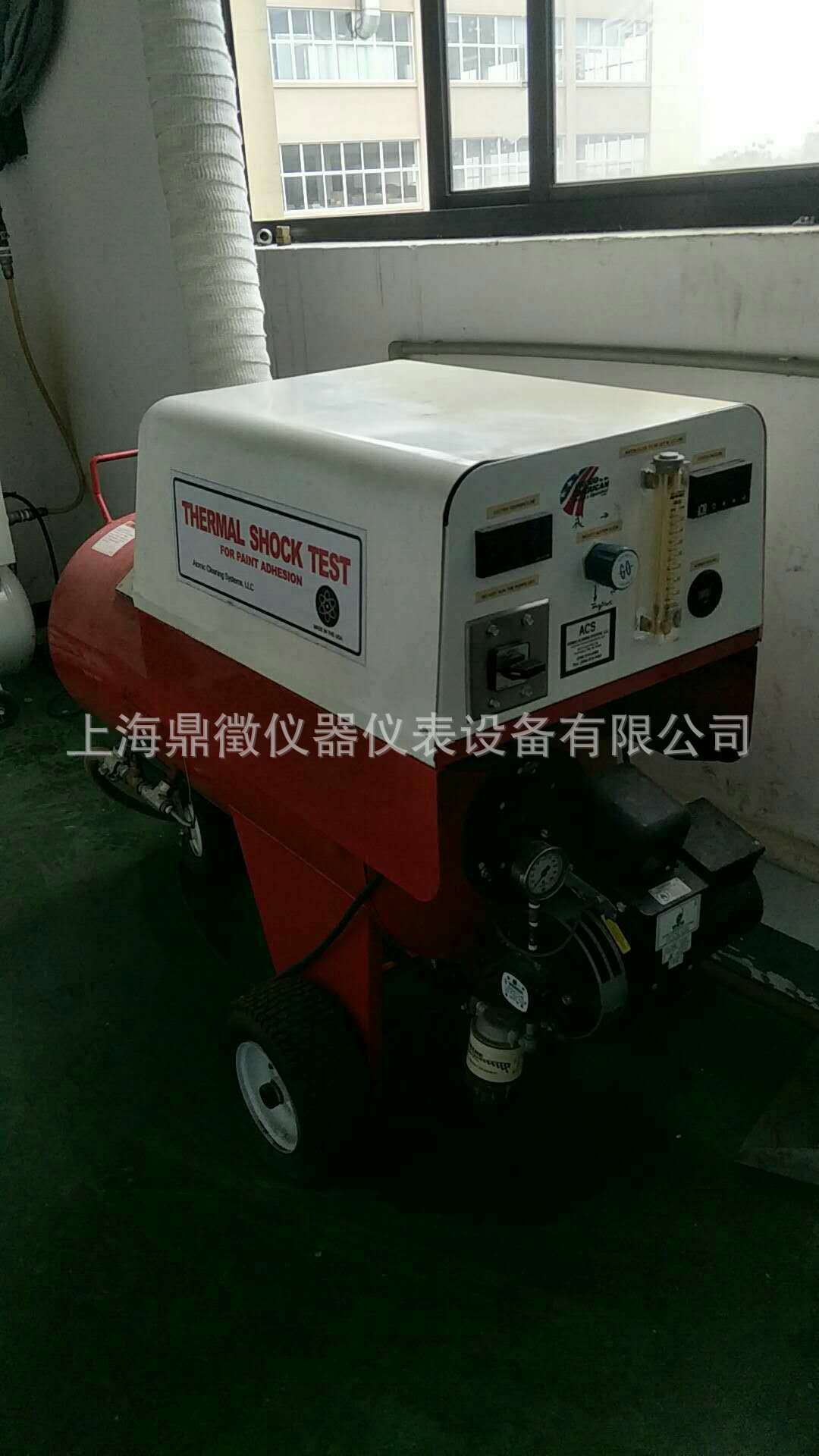
3.2.1.5 Steam generator.
Note: Model 100 (and the earlier Model 60) steam generator (from Atomic Steam Co., 10727 Fendell, Detroit MI 48238) has been found to be satisfactory. Milwaukee 1.27 cm ( 1 / 2 in) globe valve 1151 to 1161, 150 Steam Working Pressure,
300 Water-Oil-Gas, is adequate for use in standardization of generator.
3.2.1.5.1 Input Flow of Water. 2.7 L/minute with a deviation less than 5% (3.2.1.5.1.1).
3.2.1.5.1.1 Model 100 Steam Generator. The pumping pressure is directly related to the input flow rate. The pressure needed for the required flow can be determined by measuring the pump pressure and discharge flow rate with the burner off. When the burner is turned on, the required flow rate is obtained by readjusting to the required
pump pressure.
3.2.1.5.2 Nozzle Diameter. 12.5 mm ID within 2% and at least 100 mm long.
3.2.1.5.3 Discharge Dynamic Head. 37.9 kPa within ± 5% measured 25 mm from the nozzle using a 47 mm ID tube. A nondiverging discharge is required for this test (3.2.1.5.3.1 and 3.2.1.5.3.2 and Figure 1).
3.2.1.5.3.1 This is done by placing the tube midstream 25 mm from the nozzle. The tube size must not be varied because the densities and velocities are not uniform throughout the cross section of the discharge stream.
3.2.1.5.3.2 Adjusting the discharge dynamic head may be required. This must be done in such a way that the input flow rate as specified in 3.1.7.1 is maintained. This is done by adjusting the amount of heat transferred to the water. Increasing the heat will cause the input flow rate to change. It must be readjusted. This operation will result in an
increased dynamic pressure. To decrease it, decrease the heat and then adjust the flow (pressure).
3.2.1.6 Face Mask. Full face cover safety mask is required when performing this test.
3.2.1.7 Gloves. Gauntlet-type gloves for protection of hands are required.
3.3 Test Vehicle/Test Piece. Not applicable.
3.4 Test Time. Not applicable.
3.5 Test Required Information. Not applicable.
3.6 Personnel/Skills. Not applicable.
4 Procedure
4.1 Preparation. Not applicable.
4.2 Conditions. Not applicable.
4.2.1 Environmental Conditions. Not applicable.
4.2.2 Test Conditions. Deviations from the requirements of this standard shall have been agreed upon. Such requirements shall be specified on component drawings, test certificates, reports,etc.
4.3 Instructions.
4.3.1 Standardize the Model 100 steam generator.
4.3.1.1 Measure and maintain the input flow at
2.7 L/minute.
4.3.1.1.1 Install a 1.27 cm ( 1 / 2 in) globe valve in the steam line between coil weld assembly and hose nipple, 0.4 cm (5/32 in).
4.3.1.1.2 With burner off, engage pump and adjust globe valve until 2.7 L/minute is obtained.
4.3.1.1.3 Record the tank pressure that is obtained with the 2.7 L/minute flow rate. (This induced back pressure simulates the pressure that steam exerts on the system while the burner is on.)
4.3.1.2 Measure and maintain the mean dynamic head at 37.9 kPa.
4.3.1.2.1 Open globe valve and turn on the burner.
4.3.1.2.2 Allow tank pressure to stabilize before reading the mean dynamic head.
4.3.1.2.3 Adjustments of the dynamic head are to be made by changing the amount of heat transferred to the water at the burner. (The flow rate, as previously specified, must be maintained.)
4.3.2 Measure and record film thickness at proposed test sites per ISO 2808.
4.3.3 Immerse the parts or panels (previously prepared per engineering material specification) in the water immersion tank for 3 h at 38 ± 2°C.Aerate the water by placing a 6.5 ram (0.25 in) ID plastic tube at the bottom of the tank and bubble
air at a rate of 1 bubble per second minimum.Maintain 5 ppm maximum dissolved solids (as NaCl) in the water. Check and record NaCl level using dissolved solids meter.
4.3.4 Remove the samples after 3 h and immediately place in freezer at -29 ± 3°C.
4.3.5 Prepare a suitable rack to hold the test panels.
4.3.6 Following a 3 h minimum freeze cycle, remove the sample and immediately scribe an X through the coating into the substrate across the entire panel or part where feasible (Figure 2). A razor blade should be used on elastomer substrates. Mount the sample on the test rack.
4.3.7 Within 60 s from freezer removal, direct the steam blast at the scribe lines for a rain of 30 s.Angle of impingement and distance from the panel are important; care must be taken to ensure the dimensions are adhered to as follows: 45 degree
angle at a 50 to 75 mm distance (Figure 3).
4.3.7.1 High pressure wet steam represents a potential safety hazard. Not only is it necessary to secure the samples properly, but full face protection and gloves are required.
4.3.8 Remove from blast, examine, and report any loss of paint adhesion and/or any blushing (i.e., whitening, loss of gloss) and the average distance of paint adhesive loss from the scribe line.
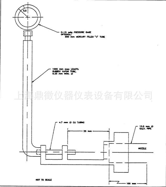
Figure 1: Measuring the Discharge Dynamic Head

Figure 2: Scribe on Panel

Figure 3: Steam Blast Impingement
5 Data
5.1 Calculations. Not applicable.
5.2 Interpretation of Results. Examine sample for any loss of paint adhesion and/or any blushing (i.e., whitening, loss of gloss) and the average distance of paint adhesive loss from the scribe line.
5.3 Test Documentation. Report any loss of paint adhesion and/or any blushing (i.e., whitening, loss of gloss) and the average distance of paint
adhesive loss from the scribe line.
6 Safety
This standard may involve hazardous materials, operations, and equipment. This standard does not propose to address all the safety problems associated with its use. It is the responsibility of the user of this standard to establish appropriate safety and health practices and determine the applicability of regulatory limitations prior to use.
7 Notes
7.1 Glossary. Not applicable.
7.2 Acronyms, Abbreviations, and Symbols. Not applicable.
8 Coding System
This standard shall be referenced in other documents, drawings, etc., as follows:
Test to GMW15919
9 Release and Revisions
9.1 Release. This standard originated in May 2008, replacing GM9525P. It was first approved by Materials Engineering in July 2009. It was first published in July 2009.
所有评论仅代表网友意见,与本站立场无关。