


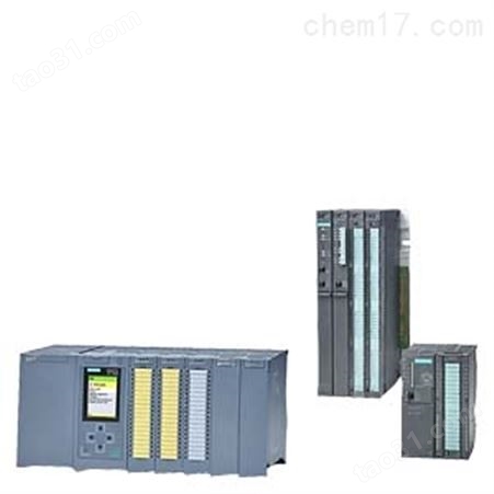
SM522数字量输出模块,西门子SM522数字量输出模块,西门子S7-1500数字量输出模块,西门子数字量输出模块,数字量输出模块
数字量输出模块可以切换设备中的 24 V DC 或 230 V AC 电压,从而可将内部信号从控制器传输至设备。可以连接电磁阀、直流接触器和指示灯。
35 mm 宽的输出模块具有可设定的参数和诊断功能,因此可根据相应过程要求进行灵活调整。
25 mm 宽的输出模块没有可设定的参数或诊断功能,因此可极为方便地集成到工程系统中。建议将它们在只需要很少输入通道的位置使用,或在必须在十分有限的空间内部署大量通道的情况下使用。
西门子原装正品 现货销售 质保一年 欢迎询价
SIEMENS 上海翰粤自动化系统有限公司
上海翰粤自动化系统有限公司是中国西门子的合作伙伴,公司主要从事工业自动化产品的集成,销售各维修。致力于为您提供在工业、化工、水泥、电力、环保等领域的电气及自动化技术的完整解决方案,包括自动化产品及系统、工程项目执行及管理、主要过程控制领域,以及专业的售后服务、培训等。
上海翰粤代理销售以下系列产品:
SIEMENS 可编程控制器
1、 SIMATIC S7 系列PLC:S7-200、S7-1200、S7-300、S7-400、ET-200,S71500
2、 逻辑控制模块 LOGO!230RC、230RCO、230RCL、24RC、24RCL等
3、 SITOP直流电源 24V DC 1.3A、2.5A、3A、5A、10A、20A、40A可并联.
4、HMI 触摸屏TD200 TD400C K-TP OP177 TP177,MP277 MP377,
SIEMENS 交、直流传动装置
1、 交流变频器 MICROMASTER系列:MM420、MM430、MM440、G110、G120.
MIDASTER系列:MDV
2、全数字直流调速装置 6RA23、6RA24、6RA28、6RA70、6SE70系列
SIEMENS 数控 伺服
SINUMERIK:801、802S 、802D、802D SL、810D、840D、611U、S120
系统及伺报电机,力矩电机,直线电机,伺服驱动等备件销售。
型号及订货号
 | 订货号:6ES7522-1BH01-0AB0 SIMATIC S7-1500, 数字量输出模块 DQ16xDC 24V/0,5A; 16 通道 8 个一组; 4A 每组; 单通道诊断; 替换值 |
 |
6ES7522-1BH10-0AA0 SIMATIC S7-1500, 数字量输出模块, DQ16xDC 24V/0,5A, 16 通道 8 个一组, 4A 每组 inkl. 前连接器 直插式 |
 |
6ES7522-1BL01-0AB0 SIMATIC S7-1500, 数字量输出模块 DQ 32xDC 24V/0,5A; 32 通道 8 个一组; 4A 每组; 单通道诊断; 替换值 |
 | 订货号:6ES7522-1BL10-0AA0 SIMATIC S7-1500, 数字量输出模块, DQ32xDC 24V/0,5A, 32 通道 8 个一组, 4A 每组 inkl. 前连接器 直插式 |
 | 订货号:6ES7522-5EH00-0AB0 SIMATIC S7-1500, 数字量输出模块 DQ16x 24...48VUC/125V DC/0.5A; 16 通道 8 个一组; 0.5A 每组; 替换值; DERATING 注意 |
 | 订货号:6ES7522-5FF00-0AB0 SIMATIC S7-1500, 数字量输出模块 DQ 8xAC 230V/2A;TRIAC; 8 通道 8 个一组; 2A 每组; 替换值 |
 | 订货号:6ES7522-5FH00-0AB0 SIMATIC S7-1500, 数字量输出模块 DQ 16xAC 230V/1A;TRIAC; 16 通道 8 个一组; 2A 每组; 替换值 |
| 订货号:6ES7522-5HF00-0AB0 SIMATIC S7-1500, 数字量输出模块 DQ 8xAC 230V/5A;继电器; 8 通道 8 个一组; 5A 每组; 诊断;替换值 |
 | 订货号:6ES7522-5HH00-0AB0 SIMATIC S7-1500, 数字量输出模块 DQ 16x 230V AC/2A ST;继电器 16 通道 8 个一组; 4A 每组; 诊断;替换值 |
概述
- 8、16 和 32 通道数字量输出模块
- 灵活地选择控制器以满足相应任务需要
- 用于使用附加输出对系统进行后续扩展
- 35 mm 宽的模块具有参数设置和诊断功能
- 25 mm 宽的模块可在狭小空间内使用:极为经济,无参数设置或诊断功能
应用
数字量输出模块可以切换设备中的 24 V DC 或 230 V AC 电压,从而可将内部信号从控制器传输至设备。可以连接电磁阀、直流接触器和指示灯。
35 mm 宽的输出模块具有可设定的参数和诊断功能,因此可根据相应过程要求进行灵活调整。
25 mm 宽的输出模块没有可设定的参数或诊断功能,因此可极为方便地集成到工程系统中。建议将它们在只需要很少输入通道的位置使用,或在必须在十分有限的空间内部署大量通道的情况下使用。
根据需要,可在一个站中并排使用两种模块。由于具有统一特性并采用共同的系统附件,处理十分方便。
提供了以下宽度为 35 mm 的数字量输出模块:
- DQ 16x24VDC/0.5A ST;
数字量输出模块,16 通道 24 VDC / 0.5 A(晶体管);两个电压组;每组 4 A;可设置诊断功能;可设置输出替代值 - DQ 32x24VDC/0.5A ST;
数字量输出模块,32 通道 24 VDC / 0.5 A(晶体管);四个电压组;每组 4 A;可设置诊断功能;可设置输出替代值 - DQ 8x24VDC/2A HF;
数字量输出模块,8 通道 24 VDC / 2 A(晶体管);四个电压组;每组 8 A;可设置诊断功能;可设置输出替代值 - DQ 8x230VAC/2A ST;
数字量输出模块,8 通道 230 VAC / 2 A(晶体管);八个电压组;每组 2 A;可设置诊断功能;可设置输出替代值 - DQ 8x230VAC/5A ST;
带有 8 点输出的数字量输出模块,230 V AC/5 A(继电器);8 个电压组;每组 5 A;可设置输出的替代值
提供了以下宽度为 25 mm 的数字量输出模块:
- DQ 16x24VDC/0.5A BA;
带有 16 个通道的数字量输出模块,24 VDC/0.5 A(晶体管);源型输出;两个电压组 4A - DQ 32x24VDC/0.5A BA;
带有 16 个通道的数字量输出模块,24 VDC/0.5 A(晶体管);源型输出;四个电压组;每组 4 A
设计
- 用一个螺丝安装在 S7-1500 安装导轨上
- 35 mm 模块 采用螺钉型端子或推入式端子的标准化 40 针前连接器(不能用于 25 mm 模块)
- 25 mm 模块 采用推入式端子的标准化 40 针前连接器(不能用于 35 mm 模块)
- 标准化、协调型前连接器针脚分配,更便于接线
- 可连接芯线截面积0.25 mm2 至 1.5 mm2(AWG24 至 16)
- 集成式电压桥接件,用于灵活形成电压组(仅 35 mm 模块)
- 前连接器的预接线位置
- 前盖带有可扩充的电缆室,即使*接线时也如此
- 模块正面的清晰标签
- 模块类型
- 订货号
- 硬件和固件型号
- 通道编号标签
- 电缆连接图
含在供货范围之内:
- 用于手工贴标签的一个标签条
- 一个 U 型连接器
- 印制有文字的前门
- 前连接器((仅 25 mm 模块)
功能
- 统一的显示和诊断方式:
- 故障(红色 LED)和运行(绿色 LED)模块状态显示
- 用于信号状态日志的信号状态显示。"0" 和日志。"1"(绿色 LED)或短路指示(红色 LED)
- 显示 24 V DC 电源电压(绿色 LED)
- 支持的功能:
- 识别和维护数据 IM0 至 IM3
- 固件更新
- 与通道有关的参数分配(仅限 HF 模块)
- 按通道进行诊断(仅限 HF 模块)
- 等时同步模式(取决于模块)
- 可以为输出设置替换值(仅限于 35 mm 模块)
技术规范
Article number | 6ES7522-1BH01-0AB0 | 6ES7522-1BL01-0AB0 | 6ES7522-1BF00-0AB0 | 6ES7522-5EH00-0AB0 | |
|---|---|---|---|---|---|
| S7-1500, DQ 16X24V DC/0.5A HF | S7-1500, DQ 32X24VDC/0.5A HF | S7-1500, DQ 8X24VDC/2A HF | S7-1500, DQ 16X24...48VUC/125VDC/0.5A ST | |
General information |
|
|
|
| |
Product type designation | DQ 16x24VDC/0.5A HF | DQ 32x24VDC/0.5A HF | DQ 8x24VDC/2A HF | DQ 16x24 ... 48VUC/125VDC/0.5A ST | |
HW functional status | FS01 | FS01 | FS01 | FS01 | |
Firmware version | V1.0.0 | V1.0.0 | V2.1.0 | V1.0.0 | |
| Yes |
| Yes | Yes | |
Product function |
|
|
|
| |
| Yes; I&M0 to I&M3 | Yes; I&M0 to I&M3 | Yes; I&M0 to I&M3 | Yes; I&M0 to I&M3 | |
Engineering with |
|
|
|
| |
| V13 SP1 / - | V13 SP1 / - | V13 SP1 / - | V13 SP1 / - | |
|
|
| V5.5 SP3 / - | V5.5 SP3 / - | |
| V1.0 / V5.1 | V1.0 / V5.1 | V1.0 / V5.1 | V1.0 / V5.1 | |
| V2.3 / - | V2.3 / - | V2.3 / - | V2.3 / - | |
Operating mode |
|
|
|
| |
| Yes | Yes | Yes | Yes | |
| No | No | Yes; with an application | No | |
| No | No | Yes | No | |
| No | No | No | No | |
| Yes | Yes | Yes | Yes | |
Supply voltage |
|
|
|
| |
Rated value (DC) | 24 V | 24 V | 24 V |
| |
permissible range, lower limit (DC) | 20.4 V | 20.4 V | 20.4 V |
| |
permissible range, upper limit (DC) | 28.8 V | 28.8 V | 28.8 V |
| |
Reverse polarity protection | Yes; through internal protection with 7 A per group | Yes; through internal protection with 7 A per group | Yes; through internal protection with 10 A per group |
| |
Input current |
|
|
|
| |
Current consumption, max. | 30 mA | 60 mA | 40 mA; 20 mA per group, no output is activated. |
| |
Output voltage |
|
|
|
| |
Rated value (DC) | 24 V | 24 V | 24 V | 24 V; 48 V, 125 V | |
Rated value (AC) |
|
|
| 24 V; 48 V (50 - 60 Hz) | |
Power |
|
|
|
| |
Power available from the backplane bus | 1.1 W | 1.1 W | 0.9 W | 2 W | |
Power loss |
|
|
|
| |
Power loss, typ. | 2 W | 3.5 W | 5.6 W; 6.8 W for PWM operation | 3.8 W | |
Digital outputs |
|
|
|
| |
Number of digital outputs | 16 | 32 | 8 | 16 | |
Current-sinking |
|
|
| Yes | |
Current-sourcing | Yes | Yes | Yes | Yes | |
Short-circuit protection | Yes; Clocked electronically | Yes; Clocked electronically | Yes |
| |
| 1 A | 1 A | 3 A |
| |
Limitation of inductive shutdown voltage to | L+ (-53 V) | L+ (-53 V) | -17 V | 200 V (suppressor diode) | |
Controlling a digital input | Yes | Yes | Yes | Yes | |
Digital output functions, parameterizable |
|
|
|
| |
|
|
| Yes |
| |
|
|
| Yes |
| |
|
|
| 2 |
| |
|
|
| Yes; 2 ... 100 ms continuous |
| |
|
|
| 0 % |
| |
|
|
| 100 % |
| |
|
|
| 0.1 % |
| |
|
|
| 300 µs |
| |
Switching capacity of the outputs |
|
|
|
| |
| 0.5 A | 0.5 A |
| 0.5 A | |
| 5 W | 5 W | 10 W | 40 W; At 125 V DC, 10 W at 48 V UC, 5 W at 24 V UC | |
Load resistance range |
|
|
|
| |
| 48 ? | 48 ? | 12 ? |
| |
| 12 k? | 12 k? | 4 k? |
| |
Output voltage |
|
|
|
| |
| L+ (-0.8 V) | L+ (-0.8 V) | L+ (-0.8 V) | L+ (-1.0 V) | |
Output current |
|
|
|
| |
| 0.5 A | 0.5 A | 2 A | 0.5 A | |
| 0.5 A | 0.5 A | 2.4 A; Note derating specification for PWM operation | 0.6 A | |
| 0.5 mA | 0.5 mA | 0.5 mA |
| |
Output delay with resistive load |
|
|
|
| |
|
|
| 80 µs |
| |
| 100 µs | 100 µs | 100 µs | 5 ms | |
|
|
| 300 µs |
| |
| 500 µs | 500 µs | 500 µs | 5 ms | |
Parallel switching of two outputs |
|
|
|
| |
| Yes | Yes | Yes | Yes | |
| No | No | No | No | |
| Yes | Yes | Yes | Yes | |
Switching frequency |
|
|
|
| |
| 100 Hz | 100 Hz | 100 Hz; With PWM operation: 500 Hz | 25 Hz | |
| 0.5 Hz; According to IEC 60947-5-1, DC-13 | 0.5 Hz; According to IEC 60947-5-1, DC-13 | 0.5 Hz; According to IEC 60947-5-1, DC-13; max. 500 Hz with PWM operation only with external circuit; see additional description in the manual | 0.5 Hz | |
| 10 Hz | 10 Hz | 10 Hz | 10 Hz | |
Total current of the outputs |
|
|
|
| |
| 0.5 A; see additional description in the manual | 0.5 A; see additional description in the manual | 2 A; see additional description in the manual | 0.5 A | |
| 4 A; see additional description in the manual | 4 A; see additional description in the manual | 8 A; see additional description in the manual | 0.5 A | |
| 8 A; see additional description in the manual | 16 A; see additional description in the manual | 16 A; see additional description in the manual | 8 A | |
Cable length |
|
|
|
| |
| 1 000 m | 1 000 m | 1 000 m | 1 000 m | |
| 600 m | 600 m | 600 m | 600 m | |
Isochronous mode |
|
|
|
| |
Isochronous operation (application synchronized up to terminal) | Yes | Yes | No | No | |
Execution and activation time (TCO), min. | 70 µs | 70 µs |
|
| |
Bus cycle time (TDP), min. | 250 µs | 250 µs |
|
| |
Interrupts/diagnostics/status information |
|
|
|
| |
Diagnostics function | Yes | Yes | Yes | No | |
Substitute values connectable | Yes | Yes | Yes | Yes | |
Alarms |
|
|
|
| |
| Yes | Yes | Yes | No | |
Diagnostic messages |
|
|
|
| |
| Yes | Yes | Yes | No | |
| Yes | Yes | No | No | |
| Yes | Yes | Yes | No | |
| Yes | Yes | Yes |
| |
Diagnostics indication LED |
|
|
|
| |
| Yes; Green LED | Yes; Green LED | Yes; Green LED | Yes; Green LED | |
| Yes; Red LED | Yes; Red LED | Yes; Red LED | Yes; Red LED | |
| Yes; Green LED | Yes; Green LED | Yes; Green LED | No | |
| Yes; Green LED | Yes; Green LED | Yes; Green LED | Yes; Green LED | |
| Yes; Red LED | Yes; Red LED | Yes; Red LED | No | |
| Yes; Red LED | Yes; Red LED | Yes; Red LED | Yes; Red LED | |
Potential separation |
|
|
|
| |
Potential separation channels |
|
|
|
| |
| No | No | No | Yes | |
| 8 | 8 | 4 | 1 | |
| Yes | Yes | Yes | Yes | |
Permissible potential difference |
|
|
|
| |
between different circuits |
|
|
| 125 V DC/48 V AC | |
Isolation |
|
|
|
| |
Isolation tested with | 707 V DC (type test) | 707 V DC (type test) | 707 V DC (type test) | 2 000 V DC | |
Ambient conditions |
|
|
|
| |
Ambient temperature during operation |
|
|
|
| |
| 0 °C |
|
| 0 °C | |
| 60 °C |
|
| 60 °C | |
| 0 °C |
|
| 0 °C | |
| 60 °C |
|
| 40 °C | |
Decentralized operation |
|
|
|
| |
Prioritized startup | Yes | Yes | Yes | Yes | |
Dimensions |
|
|
|
| |
Width | 35 mm | 35 mm | 35 mm | 35 mm | |
Height | 147 mm | 147 mm | 147 mm | 147 mm | |
Depth | 129 mm | 129 mm | 129 mm | 129 mm | |
Weights |
|
|
|
| |
Weight, approx. | 230 g | 280 g | 240 g | 230 g | |
Article number | 6ES7522-5HF00-0AB0 | 6ES7522-5HH00-0AB0 | 6ES7522-5FF00-0AB0 | 6ES7522-5FH00-0AB0 | |
|---|---|---|---|---|---|
| S7-1500, DQ 8X230VAC/5A ST (RELAY) | S7-1500, DQ 16X230VAC/2A ST (RELAY) | S7-1500, DQ 8X230VAC/2A ST (TRIAC) | S7-1500, DQ 16X230VAC/1A ST (TRIAC) | |
General information |
|
|
|
| |
Product type designation | DQ 8x230 V AC/5 A ST (relay) | DQ 16x230VAC/2A ST (relay) | DQ 8x230 V AC/2A ST (triac) | DQ 16x230VAC/1A ST (Triac) | |
HW functional status | FS01 | FS01 | FS01 | FS01 | |
Firmware version | V2.0.0 | V1.0.0 | V2.0.0 | V1.0.0 | |
| Yes | Yes | Yes | Yes | |
Product function |
|
|
|
| |
| Yes; I&M0 to I&M3 | Yes; I&M0 to I&M3 | Yes; I&M0 to I&M3 | Yes; I&M0 to I&M3 | |
Engineering with |
|
|
|
| |
| V12 / V12 | V13 SP1 / - | V12 / V12 | V13 SP1 / - | |
| V5.5 SP3 / - | V5.5 SP3 / - | V5.5 SP3 / - | V5.5 SP3 / - | |
| V1.0 / V5.1 | V1.0 / V5.1 | V1.0 / V5.1 | V1.0 / V5.1 | |
| V2.3 / - | V2.3 / - | V2.3 / - | V2.3 / - | |
Operating mode |
|
|
|
| |
| Yes | Yes | Yes | Yes | |
| No | No | No | No | |
| No | No | No | No | |
| No | No | No | No | |
| Yes | Yes | Yes | Yes | |
Supply voltage |
|
|
|
| |
Rated value (DC) | 24 V | 24 V |
|
| |
permissible range, lower limit (DC) | 20.4 V | 20.4 V |
|
| |
permissible range, upper limit (DC) | 28.8 V | 28.8 V |
|
| |
Reverse polarity protection | Yes | Yes |
|
| |
Input current |
|
|
|
| |
Current consumption, max. | 80 mA | 150 mA |
|
| |
Output voltage |
|
|
|
| |
Rated value (AC) | 230 V; 24 V DC to 120 V DC / 24 V AC to 230 V AC | 230 V; 24 V DC to 120 V DC / 24 V AC to 230 V AC | 230 V; 120/230V AC, 50/60 Hz | 230 V; 120/230V AC, 50/60 Hz | |
Power |
|
|
|
| |
Power available from the backplane bus | 0.8 W | 0.8 W | 0.9 W | 1.2 W | |
Power loss |
|
|
|
| |
Power loss, typ. | 5 W | 5 W | 10.8 W | 11.1 W | |
Digital outputs |
|
|
|
| |
Number of digital outputs | 8 | 16 | 8 | 16 | |
Current-sinking | Yes | Yes |
| Yes | |
Current-sourcing | Yes | Yes | Yes | Yes | |
Short-circuit protection | No | No | No | No | |
Controlling a digital input | possible | Yes |
|
| |
Switching capacity of the outputs |
|
|
|
| |
|
|
| 2 A | 1 A | |
| 1 500 W; 10 000 operating cycles | 50 W (230 V AC), 5 W (24 V DC) | 50 W | 50 W | |
| 10x 58 W (25 000 operating cycles) |
|
|
| |
| 1x 58 W (25 000 operating cycles) |
|
|
| |
| 10x 58 W (25 000 operating cycles) |
|
|
| |
Output voltage |
|
|
|
| |
|
|
| L1 (-1.5 V) at maximum output current; L1 (-8.5 V) at minimum output current | L1 (-1.5 V) at maximum output current; L1 (-8.5 V) at minimum output current | |
Output current |
|
|
|
| |
| 5 A | 2 A | 2 A | 1 A | |
| 5 mA; 10 V | 10 mA; 10 V | 10 mA | 10 mA | |
| 8 A; thermal continuous current | 2 A; thermal continuous current | 15 A; max. 1 AC cycle | 15 A; max. 1 AC cycle | |
| 0 A | 0 A | 2 mA | 2 mA | |
Output delay with resistive load |
|
|
|
| |
|
|
| 1 AC cycle | 1 AC cycle | |
|
|
| 1 AC cycle | 1 AC cycle | |
Parallel switching of two outputs |
|
|
|
| |
| Yes | Yes | No | No | |
| No | No | No | No | |
| Yes | Yes | Yes | Yes | |
Switching frequency |
|
|
|
| |
| 2 Hz | 1 Hz | 10 Hz | 10 Hz | |
| 0.5 Hz | 0.5 Hz | 0.5 Hz | 0.5 Hz | |
| 2 Hz | 1 Hz | 1 Hz | 1 Hz | |
Total current of the outputs |
|
|
|
| |
| 8 A; see additional description in the manual | 2 A; see additional description in the manual | 2 A; see additional description in the manual | 1 A; see additional description in the manual | |
| 8 A; see additional description in the manual | 4 A; see additional description in the manual | 2 A; see additional description in the manual | 2 A; see additional description in the manual | |
| 64 A; see additional description in the manual | 32 A; see additional description in the manual | 10 A; see additional description in the manual | 10 A; see additional description in the manual | |
Relay outputs |
|
|
|
| |
| 8 | 16 |
|
| |
| 24 V | 24 V |
|
| |
| 80 mA | 150 mA |
|
| |
| With miniature circuit breaker with characteristic B for: cos φ 1.0: 600 A cos φ 0.5 ... 0.7: 900 A with 8 A Diazed fuse: 1000 A | Miniature circuit breaker B10 / B16 |
|
| |
| No | No |
|
| |
| 5 | 5 |
|
| |
| 4 000 000; see additional description in the manual | see additional description in the manual |
|
| |
| Yes; 250 V AC/5 A g.p.; 120 V AC TV-4 tungsten; A300, R300 | No |
|
| |
Switching capacity of contacts |
|
|
|
| |
| see additional description in the manual | 2 A; see additional description in the manual |
|
| |
| see additional description in the manual | 2 A; see additional description in the manual |
|
| |
Triac outputs |
|
|
|
| |
|
|
| 5 | 4 | |
Cable length |
|
|
|
| |
| 1 000 m | 1 000 m | 1 000 m | 1 000 m | |
| 600 m | 600 m | 600 m | 600 m | |
Isochronous mode |
|
|
|
| |
Isochronous operation (application synchronized up to terminal) | No | No | No | No | |
Interrupts/diagnostics/status information |
|
|
|
| |
Diagnostics function | Yes | Yes | No | No | |
Substitute values connectable | Yes | Yes | Yes | Yes | |
Alarms |
|
|
|
| |
| Yes | Yes | No | No | |
Diagnostic messages |
|
|
|
| |
| Yes | Yes | No | No | |
| No | No | No | No | |
| No | No | No | No | |
Diagnostics indication LED |
|
|
|
| |
| Yes; Green LED | Yes; Green LED | Yes; Green LED | Yes; Green LED | |
| Yes; Red LED | Yes; Red LED | Yes; Red LED | Yes; Red LED | |
| Yes; Green LED | Yes; Green LED | No | No | |
| Yes; Green LED | Yes; Green LED | Yes; Green LED | Yes; Green LED | |
| No | No | No | No | |
| Yes; Red LED | Yes; Red LED | Yes; Red LED | Yes; Red LED | |
Potential separation |
|
|
|
| |
Potential separation channels |
|
|
|
| |
| Yes; Switching of different phases permitted | No | Yes | No | |
| 1 | 2 | 1 | 2 | |
| Yes | Yes | Yes | Yes | |
| Yes | Yes |
|
| |
|
|
| Yes |
| |
Permissible potential difference |
|
|
|
| |
between different circuits | 250 V AC between the channels and the supply voltage L+; 250 V AC between the channels and the backplane bus; 500 V AC between the channels | 250 V AC between the channels and the supply voltage L+; 250 V AC between the channels and the backplane bus; 500 V AC between the channels | 250 V AC between the channels and the backplane bus; 500 V AC between the channels | 250 V AC between the channels and the backplane bus; 500 V AC between the channels | |
Isolation |
|
|
|
| |
Isolation tested with | Between channels: 3 100 V DC; between channels backplane bus: 3 100 V DC; between L+ and backplane bus: 707 V DC (type test) | Between channels: 3 100 V DC; between channels backplane bus: 3 100 V DC; between L+ and backplane bus: 707 V DC (type test) | 3 100 V DC | 3 100 V DC | |
Ambient conditions |
|
|
|
| |
Ambient temperature during operation |
|
|
|
| |
| 0 °C | 0 °C | 0 °C | 0 °C | |
| 60 °C | 60 °C | 60 °C | 60 °C | |
| 0 °C | 0 °C | 0 °C | 0 °C | |
| 40 °C | 40 °C | 40 °C | 60 °C | |
Decentralized operation |
|
|
|
| |
Prioritized startup | Yes | Yes | Yes | Yes | |
Dimensions |
|
|
|
| |
Width | 35 mm | 35 mm | 35 mm | 35 mm | |
Height | 147 mm | 147 mm | 147 mm | 147 mm | |
Depth | 129 mm | 129 mm | 129 mm | 129 mm | |
Weights |
|
|
|
| |
Weight, approx. | 350 g | 350 g | 290 g | 310 g | |
Article number | 6ES7522-1BH10-0AA0 | 6ES7522-1BL10-0AA0 | |
|---|---|---|---|
| S7-1500, DQ 16X24VDC/0.5A BA | S7-1500, DQ 32X24VDC/0.5A BA | |
General information |
|
| |
Product type designation | DQ 16x24VDC/0.5A BA | DQ 32x24VDC/0.5A BA | |
HW functional status | FS01 | FS01 | |
Firmware version | V1.0.0 | V1.0.0 | |
| Yes | Yes | |
Product function |
|
| |
| Yes; I&M0 to I&M3 | Yes; I&M0 to I&M3 | |
Engineering with |
|
| |
| V13 / V13 | V13 / V13 | |
| V5.5 SP3 / - | V5.5 SP3 / - | |
| V1.0 / V5.1 | V1.0 / V5.1 | |
| V2.3 / - | V2.3 / - | |
Operating mode |
|
| |
| Yes | Yes | |
| No | No | |
| No | No | |
| No | No | |
| Yes | Yes | |
Supply voltage |
|
| |
Rated value (DC) | 24 V | 24 V | |
permissible range, lower limit (DC) | 20.4 V | 20.4 V | |
permissible range, upper limit (DC) | 28.8 V | 28.8 V | |
Reverse polarity protection | Yes; through internal protection with 7 A per group | Yes; through internal protection with 7 A per group | |
Input current |
|
| |
Current consumption, max. | 30 mA | 60 mA | |
Output voltage |
|
| |
Rated value (DC) | 24 V | 24 V | |
Power |
|
| |
Power available from the backplane bus | 1.15 W | 1.15 W | |
Power loss |
|
| |
Power loss, typ. | 2.2 W | 3.8 W | |
Digital outputs |
|
| |
Number of digital outputs | 16 | 32 | |
Current-sourcing | Yes | Yes | |
Short-circuit protection | Yes | Yes | |
| 1 A | 1 A | |
Limitation of inductive shutdown voltage to | L+ (-53 V) | L+ (-53 V) | |
Controlling a digital input | Yes | Yes | |
Switching capacity of the outputs |
|
| |
| 0.5 A | 0.5 A | |
| 5 W | 5 W | |
Load resistance range |
|
| |
| 48 ? | 48 ? | |
| 12 k? | 12 k? | |
Output voltage |
|
| |
| L+ (-0.8 V) | L+ (-0.8 V) | |
Output current |
|
| |
| 0.5 A | 0.5 A | |
| 0.5 A | 0.5 A | |
| 0.5 mA | 0.5 mA | |
Output delay with resistive load |
|
| |
| 100 µs | 100 µs | |
| 500 µs | 500 µs | |
Parallel switching of two outputs |
|
| |
| Yes | Yes | |
| No | No | |
| Yes | Yes | |
Switching frequency |
|
| |
| 100 Hz | 100 Hz | |
| 0.5 Hz; According to IEC 60947-5-1, DC-13 | 0.5 Hz; According to IEC 60947-5-1, DC-13 | |
| 10 Hz | 10 Hz | |
Total current of the outputs |
|
| |
| 0.5 A; see additional description in the manual | 0.5 A; see additional description in the manual | |
| 4 A; see additional description in the manual | 4 A; see additional description in the manual | |
| 8 A; see additional description in the manual | 16 A; see additional description in the manual | |
Cable length |
|
| |
| 1 000 m | 1 000 m | |
| 600 m | 600 m | |
Isochronous mode |
|
| |
Isochronous operation (application synchronized up to terminal) | No | No | |
Interrupts/diagnostics/status information |
|
| |
Diagnostics function | No | No | |
Substitute values connectable | No | No | |
Alarms |
|
| |
| No | No | |
Diagnostic messages |
|
| |
| No | No | |
| No | No | |
| No | No | |
| No | No | |
Diagnostics indication LED |
|
| |
| Yes; Green LED | Yes; Green LED | |
| Yes; Red LED | Yes; Red LED | |
| Yes; Green LED | Yes; Green LED | |
| Yes; Green LED | Yes; Green LED | |
| No | No | |
| No | No | |
Potential separation |
|
| |
Potential separation channels |
|
| |
| No | No | |
| 8 | 8 | |
| Yes | Yes | |
Isolation |
|
| |
Isolation tested with | 707 V DC (type test) | 707 V DC (type test) | |
Decentralized operation |
|
| |
Prioritized startup | Yes | Yes | |
Dimensions |
|
| |
Width | 25 mm | 25 mm | |
Height | 147 mm | 147 mm | |
Depth | 129 mm | 129 mm | |
Weights |
|
| |
Weight, approx. | 230 g | 280 g | |
Other |
|
| |
Note: | Supplied incl. 40-pole push-in front connectors | Supplied incl. 40-pole push-in front connectors | |


所有评论仅代表网友意见,与本站立场无关。